
Flight Science & Technology Research Group
Evaluation and Analysis of Helicopter Handling Qualities in the Degraded Visual Environment
Department Home
Page
Courses
Simulation
Facilities
Feedback: mdw@liv.ac.uk
OVERVIEW
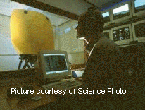 The
effectiveness of typical helicopter missions like Search and
Rescue or transport missions are highly dependant on the ability
to fly the aircraft at any time. One critical issue is the
Degraded Visual Environment (DVE). The DVE encompasses reduced
visibility due to weather conditions (e.g. rain, fog) and near
zero visibility if it happens to be a dark night. In such a
situation the pilot misses important visual cues pertaining to
their flight trajectory. Pilot workload increases significantly,
and safety is endangered (especially in Near Earth operations).
The cueing deficit must be compensated with a higher level of
helicopter stability and/or by using a pilot vision aid.
The
effectiveness of typical helicopter missions like Search and
Rescue or transport missions are highly dependant on the ability
to fly the aircraft at any time. One critical issue is the
Degraded Visual Environment (DVE). The DVE encompasses reduced
visibility due to weather conditions (e.g. rain, fog) and near
zero visibility if it happens to be a dark night. In such a
situation the pilot misses important visual cues pertaining to
their flight trajectory. Pilot workload increases significantly,
and safety is endangered (especially in Near Earth operations).
The cueing deficit must be compensated with a higher level of
helicopter stability and/or by using a pilot vision aid.
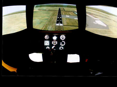 Active
Control Technologies can be applied to provide the required
level of
Handling
Qualities
by
means of Advanced control laws on fly-by-wire or fly-by-light
helicopters. These concepts include the ‘Attitude-command
(AC), the ‘Transitional-Rate-Command (TRC)’ and the
‘Positional-Command (PC)’ for hover.
Operations in reduced visibility or by night are made possible by using vision sensors like Night Vision Goggles (NVG) or Forward Looking Infrared Radar (FLIR). These sensors utilise artificial vision to improve the cues available to the pilot. Advanced displays that allow low workload Nap-of-the-Earth flight (NoE) are not yet available. Current sensor technologies cannot yet compensate for all the cueing deficiencies, and hence the DVE has a degrading effect on Handling Qualities.
Insufficient work has been completed to date to analyse handling qualities in a degraded visual environment. The Aeronautical Design Standard for military helicopters ‘ADS33’ proposes an approach to deal with this problem. However, this approach needs to be tested,evaluated and improved if necessary
To apply and evaluate the existing ADS33 specifications in DVE. Firstly, in a piloted simulation environment, and then in a real situation during flight tests.
Relation
between Usable Cue Environment and Response Types
according to Aeronautical Design Standard 33
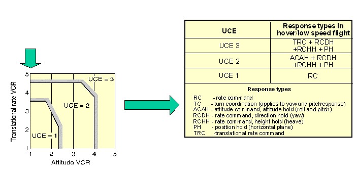
Figure 1
The DVE is a facet of the Usable Cue Environment (UCE). The UCE ‘to date’ is primarily used in helicopter mission design to ascertain the required Response Types for hover and low speed near earth operations (Figure 1).
UCE required response type process:
-
Obtain Visual Cue Ratings (VCRs) from at least 3 test pilots in the environment in question (Attitude and Translational rate). VCRs range from ‘1’ (very good) to ‘5’ (poor).
-
Plot on the UCE chart to determine overall UCE rating. UCE ratings range from UCE 1 (good) to UCE 3 (poor).
-
Determine Response Type required for aircraft mission.
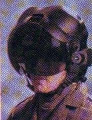 Safe
operations in DVE can be made possible by using Vision Aids to
synthetically improve the visual cues. Vision aids may be
provided to the pilot through multiple channels; helmet visor
(Figure 2), cockpit panels, head-up and head-down displays.
Such vision aids should work in harmony with existing systems
like overlaid symbology, and should remain simple to prevent
information overload.
Firstly; In order to create a ‘Good’ visual aid that would present all the necessary information to the pilot, it is of paramount importance to understand how pilots use visual cues to manoeuvre the aircraft. Here, A time-to-contact (temporal) method is preferred over a distance-to-contact (spatial) representation of the environment external of the aircraft.
Figure 2
OPTICAL TAU
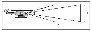
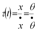
Figure 3 Equation 1
TAU-COUPLING
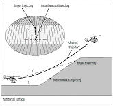
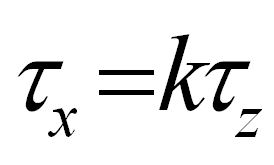
Figure 4 Equation 2
INTRINSIC MOTION GUIDES
Activated in situations where there is a single dominant gap. Closure of a single motion gap is controlled by keeping the Tau of the motion gap coupled to an intrinsically generated Tau-guide.
VISION AIDS DEVELOPMENT
Members:
Mr Gary Clark Research Student