| |
||||||||||
| FLIGHT SCIENCE AND TECHNOLOGY | ||||||||||
| The Department of Engineering | Flight Science and Technology Group | OPTIMAL | Encounter Modelling | ||||||||||
|
|
||||||||||
|
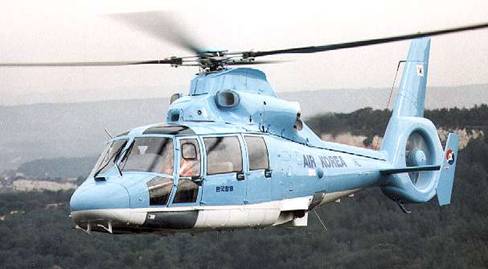
OPTIMAL Wake Vortex Encounter Modelling The rotorcraft simulation used for the research is a model of the Eurocopter AS365N1 Dauphin helicopter. The Dauphin (below) is a medium-weight multipurpose twin-engine helicopter that features a four blade main rotor and a ‘FENESTRON’ ducted fan tail rotor.
Eurocopter AS365N2 Dauphin helicopter The main technical specifications of the Dauphin are as follows:
The Dauphin simulation was created using FLIGHTLAB (www.flightlab.com), which is an advanced software package that uses a multi-body dynamic approach to modelling flight vehicles. A modular approach is used where the rotor, fuselage, empennage, fin, engines and flight control system are individual subsystems made up of ‘components’. Each component is a modelling primitive, i.e. airfoil, hinge, mass, translate and by connecting these together, complex dynamic systems can be rapidly generated. The Dauphin FLIGHTLAB model is currently a medium fidelity model with the following features:
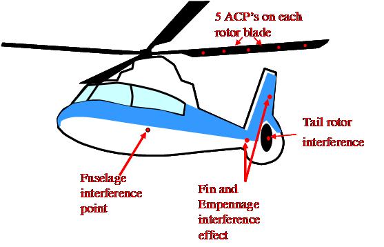
The FLIGHTLAB Dauphin helicopter simulation interacts with the vortex through a number aerodynamic computation points or ACP’s. In total there are 24 distributed locations on the model which ‘see’ the flow velocities of the wake vortex. These consist of 5 aerodynamic points on the four rotor blades, one for the tail rotor at the hub, one each for the fin and empennage, and one at the fuselage ACP. The vortex velocities are added to the inertial velocities and any induced inflow and/or interference velocities at each ACP.
Aerodynamic Interference Points for Wake Vortex Interaction Simulation |
||||||||||