Ion Channel / steroid undergraduate project
University of Birmingham, Physiology Department.
Ref: Dr. Richard Barrett-Jolley
Potassium channel voltage patch clamp introduction.
Kv 1.1 is a typical delayed rectifier channel, i.e., its opening allows potassium exit and repolarisation of the membrane potential.
Kv 1.1 is a voltage-gated channel. "Voltage gated" means that opening and/or closing is/are controlled by membrane voltage. In the case of Kv1.1 channels open as the membrane becomes less negative and re-close once the membrane returns towards the resting membrane potential.
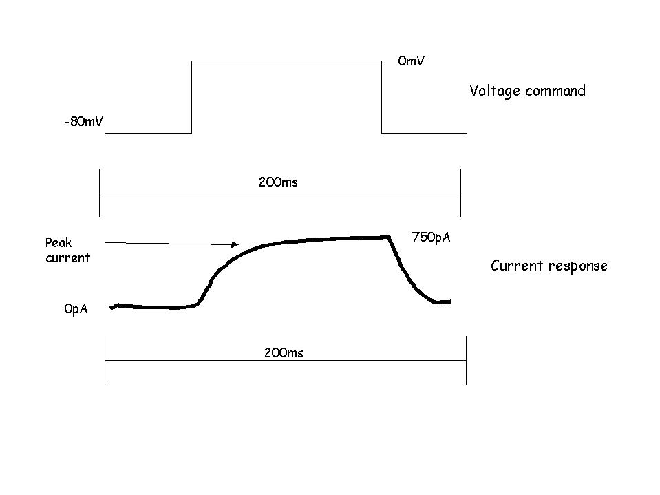
In this project, you will control the cells’ membrane potential (the "voltage-clamp" technique) and measure the resulting flow of current. This is almost the reverse of what happens in nature, but useful for characterising ion channel function. Firstly, you will hold the membrane potential near a typical resting membrane potential (-80mV) and, using the PC/amplifier equipment, step the membrane potential to various (relatively) positive levels…
During the course of this short (5th of a second) voltage pulse current will increase;
You will find that steps from the "holding potential" to different "command potentials" evoke different size current responses.
How Big Will The Current be ?
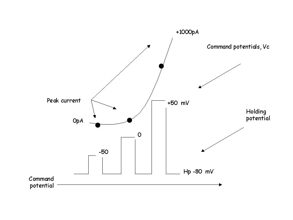
The current response size depends on the following factors; (i) the number of channels in the cell membrane, (ii) the size of the individual channels, (iii) the proportion of channels which are open, (iv) the ionic "driving force".
NB., For a given channel type (eg., Kv1.1) the channels are all the same size and for a given experiment, the number of channels remains constant. This means that for each voltage step the size of the current is dependent on the proportion of channels that open and the ionic driving force.
(1) How Many Channels Open?
The more you depolarise, the more channels that open, until they’re pretty much all open. Rather than talk of the number of channels open (which you can’t easily measure), it is more usual to talk of conductance. Its proper units are siemens, however, sometimes it is easier to talk of relative conductance on a scale of 0 (all channels closed) to 1.0 (all channels open). For a Kv channel, this increases with voltage sigmoidally.
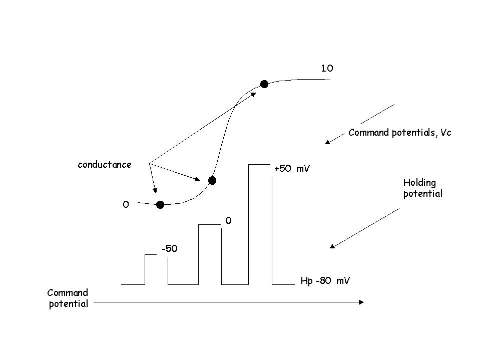
This conductance-voltage relationship is a Boltzman curve. It contains a lot of information and will be the first place to look for action of steroids.
(2) The Ionic Driving Force
The ionic driving force is the difference (in mV) between command potential and the potassium equilibrium potential (calculated with the Nernst equation, approx. –90mV). The potassium equilibrium will of course remain constant throughout an experiment, but the ionic driving force will be different for each different voltage step.
So with increasingly large voltage steps both the driving force and the number of channels open increase resulting in much greater current size. These two factors can be easily separated with post experiment analysis.
What is the time course of the potassium current?
Generally, a voltage step command does not result in an instantaneous current (there are exceptions to this rule!!). Instead, current develops over the course of milliseconds, or tens of milliseconds. This fairly progressive activation of ionic current results from the progressive opening (gating) of ion channels. The change in driving force is pretty much instantaneous (again there are exceptions to this). Still more generally, the rate at which channels open (and current develops) is greater with larger voltage steps. It will be important to measure the rate at which current develops and investigate whether steroids alter this.
Some potassium currents also inactivate during the course of a voltage pulse. Again, steroids could potentially alter this inactivation.
Capacity transients etc., … flies in the ointment.
The primary difficulty with patch clamp experiments of this kind is that of "series resistance", "voltage –drop", "capacity compensation", "leak" etc.. All these will be explained, but you should be aware that some portions of the recorded current signal result from "leak currents", or "capacity transients"…. And that the command potential you send to the cell (via the amplifier) may not actually be the same as the voltage pulse received by the cell.
Project patch-clamp protocols.
This is just a loose guide. You will be shown all this explicitly.
Cell culture
Recording
Analysis