| |
|
|
||||||||||||
| |
||||||||||||||
|
|
|
|
|||||||||||
| Electronics - AS Module 1 & 2 Power
The Units of Power are Joules per Second ( J/s)
But also Energy Transferred = Charge x Voltage E = Q x V And so Electrical Power = (Charge x Voltage)÷ Time Taken P = (Q x V) / t But Charge / time taken = Electric Current Q/t = I And so the expression for Electrical Power becomes Power = Current x Voltage P = I x V Resistance
This resistance is measured in ohms, . Definition -“If it takes 1 volt (1 joule per coulomb) to push a current of 1amp through a resistor, it has a resistance of 1 ohm” In equation form, that says R=V/I Otherwise written as the more familiar V=IR This equation summarises Ohm’s law. It suggests that any value of voltage you put across a resistor divided by the current it produces in the resistor, will always give the same value of resistance. So, if you plotted a graph you would get:
Any resistor that does this is called an ohmic resistor. Any resistor that doesn’t do this is therefore called a non-ohmic resistor. A
filament lamp (non-ohmic).
A
diode (non-ohmic). Combination of Resistors in Circuits, Parallel and SeriesSeries
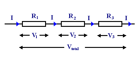
Current used in all 3 will be the same (current doesn’t get used up) but energy used per coulomb (i.e. pd) will depend on value of resistance So, Vtotal = V1 + V2 + V3 and as V = IR IRtotal = IR1 + IR2 + IR3 canel the I's Rtotal = R1 + R2 + R3 Parallel
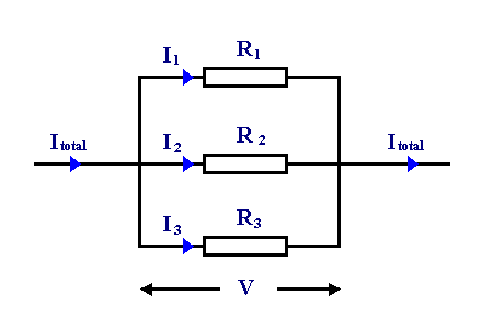
Here the voltage across all three will be the same but current through each depends on resistance of each. So Itotal = I1+ I2 + I3 and as I=V/R V/Rtotal = V/R1 + V/R2 + V/R3 Cancel the V’s to get: 1/Rtotal = 1/R1 + 1/R2 + 1/R3
Diodes A diode is a semiconductor device which allows current to flow through it in only one direction. Although a transistor is also a semiconductor device, it does not operate the way a diode does. A diode is specifically made to allow current to flow through it in only one direction.There are a number of different electronic devices which tend to be called diodes. Although they're made differently they all have three things in common.
The following are some examples of common diodes: Voltage
regulation diode (Zener Diode)
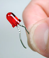
The circuit symbol is . It is used to regulate voltage, by taking advantage of the fact that Zener diodes tend to stabilize at a certain voltage when that voltage is applied in the opposite direction. Light emitting diode
The
circuit symbol is . This
type of diode emits light when current flows through it in the forward
direction. (Forward biased.) Variable capacitance diode
The current does not flow when applying the voltage of the opposite direction to the diode. In this condition, the diode has a capacitance like the capacitor. It is a very small capacitance. The capacitance of the diode changes when changing voltage. With the change of this capacitance, the frequency of the oscillator can be changed. Characteristics of a LED
The value of the external resistor is given by
The graph below the electrical characteristics of a typical diode.
When
a small voltage is applied to the diode in the forward direction,
current flows easily. When
voltage is applied in the reverse direction through a diode, the
diode will have a great resistance to current flow. Uses of Diodes
Diodes are used in many electronic circuits. Light
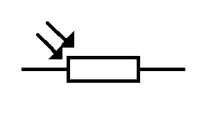
Dependent Resistor (LDR)
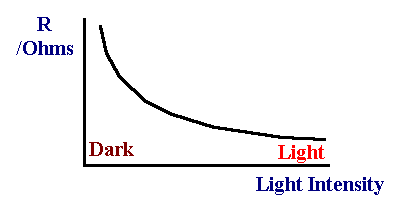
Characteristics of the LDR
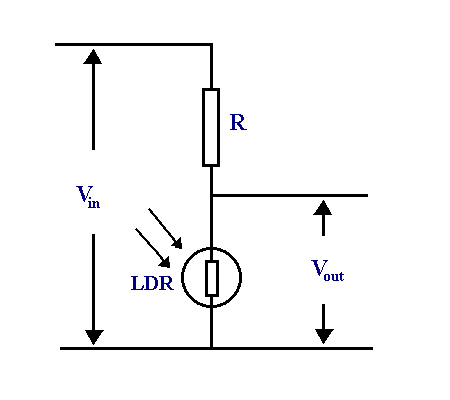
LDR as arranged in a potential divider
Vout/Vin
= Rldr / R + Rldr Thermistor
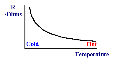
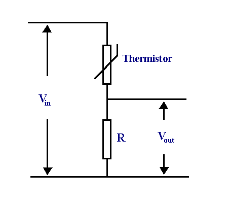
Characteristics of a Thermistor
The resistance of a Thermistor decreases as the temperature goes
up.
Measuring temperature - thermometer. Vout/Vin
= R/ Rth+ R
|
|
|||||||||||||
| |
||||||||||||||
| |
|
|
|
|
||||||||||


